Understanding the Wilkinson Power Divider: A Key Component in RF Engineering
The Wilkinson power divider stands as a cornerstone in the realm of radio frequency (RF) engineering, offering a reliable method to split microwave signals with minimal loss and high isolation. Invented by Ernest J. Wilkinson in 1960, this device has become indispensable for applications requiring precise signal distribution. Whether you're designing communication systems or testing RF components, grasping the fundamentals of the Wilkinson power divider can enhance your project's efficiency and performance. This article delves into its design, applications, and advantages, shedding light on why it's a go-to solution in modern RF setups.
Design Principles of the Wilkinson Power Divider
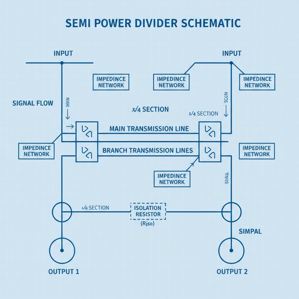
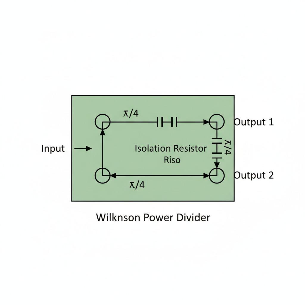
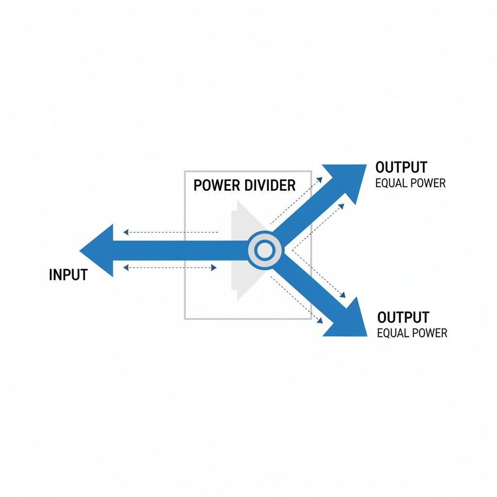
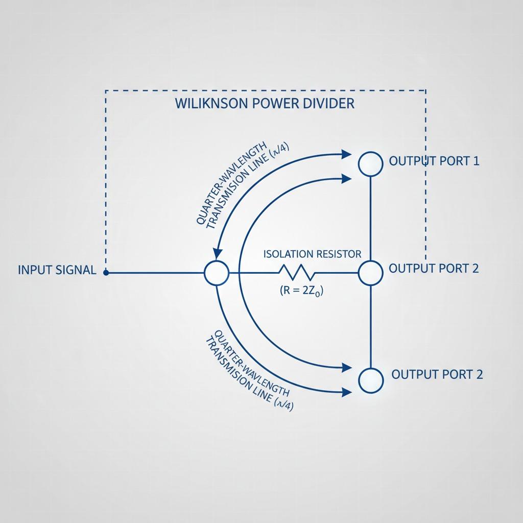
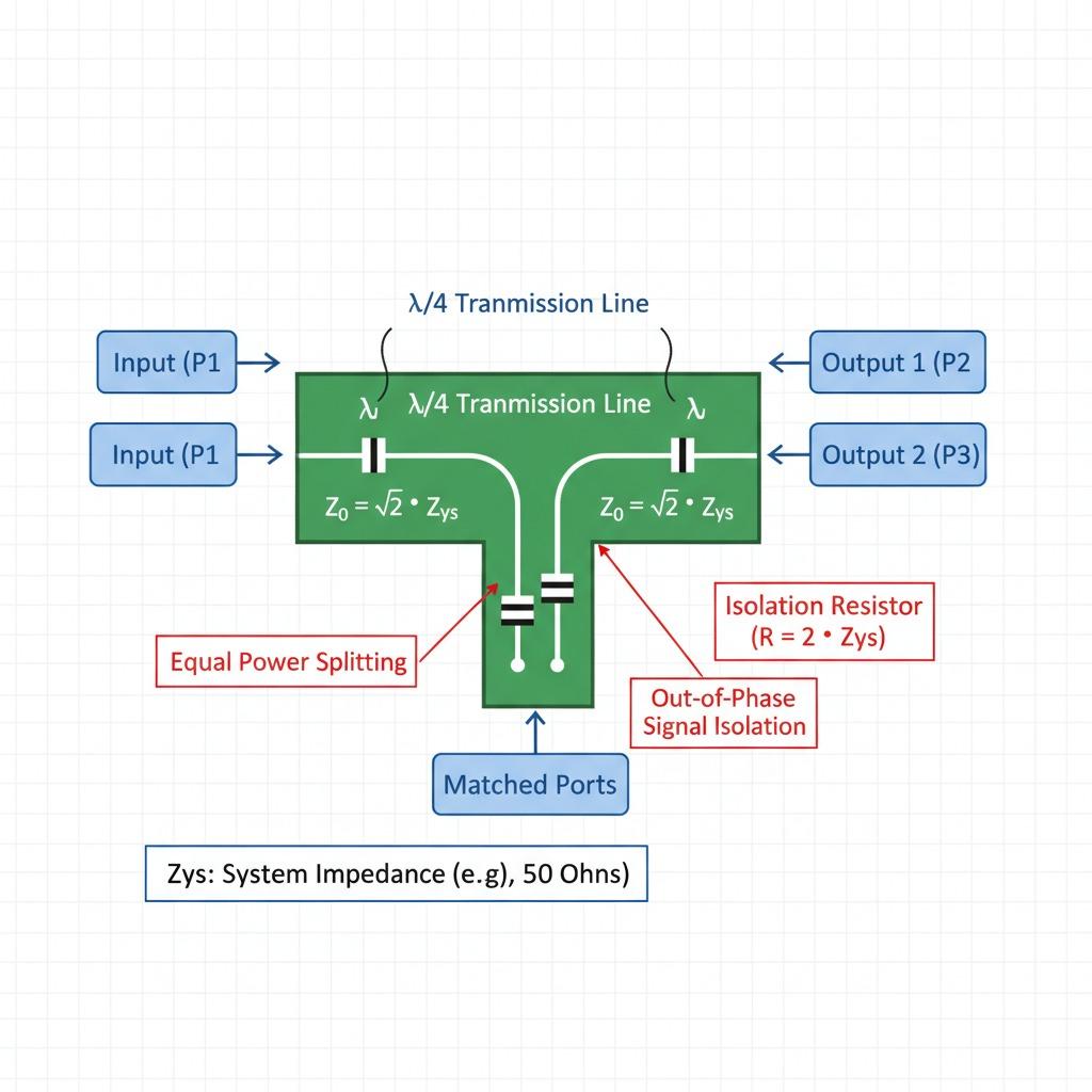
At its core, the Wilkinson power divider operates on the principles of transmission line theory, utilizing quarter-wavelength transmission lines and isolation resistors to achieve equal power splitting. Typically configured as a two-way divider, it takes an input signal and divides it into two output ports with a 3 dB attenuation per path, ensuring that the power is split equally without introducing phase differences between the outputs. The key to its success lies in the 50-ohm characteristic impedance of the lines and a 100-ohm resistor connected between the output ports, which provides isolation and prevents signal reflection back to the input.
This design not only minimizes insertion loss but also offers excellent return loss, often exceeding 20 dB across a broad bandwidth. For a basic Wilkinson power divider, the center frequency determines the length of the quarter-wave lines, making it tunable for specific operational bands like those in microwave frequencies. Advanced variants, such as multi-section or asymmetric designs, extend its bandwidth up to octave ranges, accommodating diverse RF power divider needs in complex systems. Engineers appreciate its simplicity, as it can be fabricated using microstrip or stripline techniques on standard PCB materials, keeping costs low while maintaining high performance.
Applications of the Wilkinson Power Divider
Power divider application spans a wide array of fields, from telecommunications to radar systems, where the Wilkinson power divider excels in feeding antennas or combining signals in amplifiers. In cellular base stations, for instance, it ensures that transmitted power is evenly distributed to multiple antenna elements, enhancing coverage and reducing interference. Its ability to handle high power levels makes it suitable for military and satellite communications, where reliability under demanding conditions is paramount.
In laboratory environments, the RF power divider variant of the Wilkinson design is crucial for signal testing and measurement setups. Vector network analyzers often incorporate these dividers to split signals for simultaneous port measurements, allowing precise characterization of devices under test. Moreover, in microwave power divider contexts, it's used in phased array radars to distribute local oscillator signals, maintaining phase coherence across elements for accurate beam steering. The device's low VSWR (Voltage Standing Wave Ratio) ensures that signals remain clean, minimizing distortions that could compromise system accuracy.
Beyond traditional uses, emerging applications in 5G networks leverage the Wilkinson power divider for massive MIMO systems, where multiple signals must be split and routed efficiently. Its integration into monolithic microwave integrated circuits (MMICs) has further miniaturized devices, enabling compact designs in IoT sensors and wearable tech. As frequencies push into millimeter-wave bands, modified Wilkinson structures with lumped elements are being explored to overcome fabrication challenges at higher GHz ranges.
Advantages and Limitations in RF and Microwave Systems
One of the primary advantages of the Wilkinson power divider is its superior port-to-port isolation, typically better than 20 dB, which prevents crosstalk between outputs—a critical feature in multi-channel systems. This isolation, coupled with broadband matching, makes the microwave power divider version ideal for harmonic suppression in nonlinear circuits like mixers and multipliers. Additionally, its passive nature means no additional power supply is required, simplifying integration and reducing overall system complexity.
Compared to other dividers like the branch-line or rat-race couplers, the Wilkinson offers better amplitude balance and higher power-handling capability, especially in high-frequency RF power divider applications. It's also more forgiving in terms of fabrication tolerances, as small variations in line lengths have minimal impact on performance at the design frequency. However, limitations exist: its bandwidth is inherently narrow for single-section designs, often limited to 10-20% around the center frequency, necessitating multi-section implementations for wider bands.
Another consideration is the resistor's power dissipation; in high-power scenarios, it can generate heat, requiring thermal management. Despite these, ongoing research into hybrid and active Wilkinson power dividers addresses such issues, incorporating amplifiers for loss compensation and extending usability into sub-terahertz regimes. For engineers, selecting the right configuration involves balancing bandwidth, power rating, and size constraints tailored to the specific power divider application.
Implementing the Wilkinson Power Divider in Modern Designs
When implementing a Wilkinson power divider, simulation tools like ADS or HFSS are invaluable for optimizing layout and verifying performance before prototyping. Start by defining the center frequency and desired bandwidth; for a 2.4 GHz Wi-Fi application, quarter-wave lines would be approximately 31 mm long on FR4 substrate. Adding vias for grounding and careful resistor placement ensures the isolation resistor functions effectively.
In practice, testing involves measuring S-parameters: S11 for input match, S21 and S31 for power split, and S23 for isolation. Real-world results often show insertion loss slightly above the ideal 3 dB due to substrate losses, but this is manageable with low-loss materials like Rogers RO4000. For power divider application in combiners—by reversing the ports—the same design handles signal summation with equal efficacy, useful in balanced amplifiers.
As RF systems evolve with higher data rates and integration demands, the Wilkinson's adaptability shines. Custom designs for specific RF power divider needs, such as dual-band operation, use cascaded sections or folded structures to meet compact form factors. Educational resources and open-source models further democratize its use, allowing hobbyists and professionals alike to experiment and innovate.
Future Trends and Innovations
Looking ahead, the Wilkinson power divider continues to evolve with advancements in materials and fabrication. Metamaterials and 3D printing enable ultra-compact versions for microwave power divider roles in drones and autonomous vehicles. Integration with GaN technology boosts power handling for next-gen radars, while AI-driven optimization refines designs for minimal loss.
In summary, the Wilkinson power divider remains a versatile, efficient solution for splitting and combining RF signals. Its proven track record in power divider application underscores its enduring value in engineering landscapes, from everyday wireless devices to cutting-edge aerospace systems. By understanding its principles and applications, designers can harness its full potential to drive innovation and reliability.