Understanding the Semi Power Divider: A Key Component in RF Engineering
In the world of radio frequency (RF) engineering, the semi power divider stands out as a versatile and efficient device used to split incoming signals into multiple paths with minimal loss. Often employed in communication systems, radar applications, and wireless networks, this component ensures that power is distributed evenly, maintaining signal integrity across various frequencies. As technology advances, the semi power divider has become indispensable for designs requiring compact, high-performance solutions. Whether you're a design engineer or simply curious about RF components, grasping its fundamentals can illuminate its role in modern electronics.
What is a Semi Power Divider?
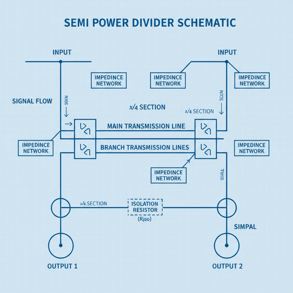
A semi power divider, sometimes referred to in contexts overlapping with RF power dividers, is a passive device designed to divide an input signal into two or more output signals of equal or specified power levels. Unlike full-wave or balanced dividers, the semi power divider often incorporates hybrid designs that blend transmission line principles with lumped elements, offering a balance between size and bandwidth. This makes it particularly suitable for mid-range frequency applications, such as those in the 1-10 GHz spectrum. The core principle behind its operation is impedance matching, where the input impedance equals the output to prevent reflections and signal degradation. Engineers appreciate its semi-rigid construction, which allows for flexibility in integration into circuit boards without sacrificing durability.
In practical terms, a semi power divider functions by using quarter-wave transmission lines or similar structures to achieve the division. For instance, when an RF signal enters the device, it encounters a junction that splits the energy symmetrically. This symmetry is crucial for phase coherence, ensuring that the output signals remain in sync for applications like antenna arrays. Compared to more rigid dividers, the semi version provides some tolerance in mounting and alignment, which is beneficial in prototyping stages. Its efficiency can reach up to 90% in well-designed units, minimizing insertion loss and maximizing system performance.
Exploring the RF Power Divider Family
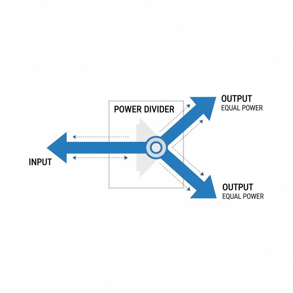
The RF power divider is the broader category encompassing devices like the semi power divider, serving as the backbone for signal distribution in RF systems. These dividers are essential in scenarios where a single source needs to feed multiple receivers or amplifiers, such as in satellite communications or cellular base stations. An RF power divider typically operates by splitting power in ratios like 1:1 or 1:2, depending on the design requirements. High-quality models feature low VSWR (Voltage Standing Wave Ratio), often below 1.5:1, which indicates excellent matching and reduced energy bounce-back.
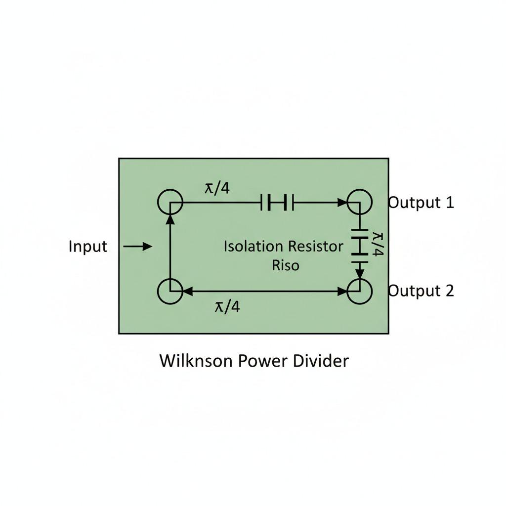
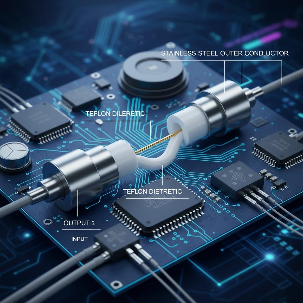
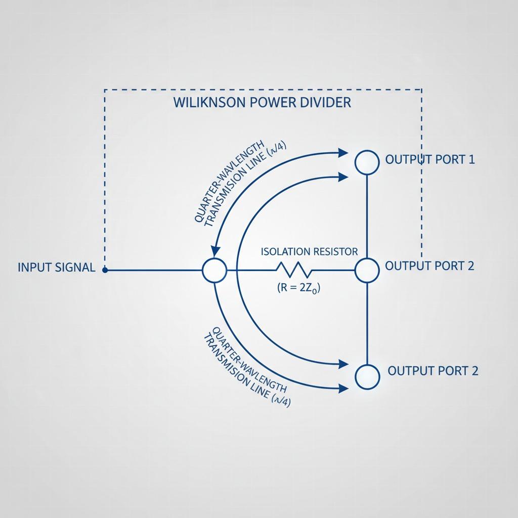
Within this family, variations like Wilkinson dividers are popular for their isolation between output ports, preventing crosstalk that could degrade signal quality. The RF power divider's versatility extends to both combining and dividing functions; in reverse, it can merge signals from multiple sources into one, useful in feedback loops or multi-channel transmitters. Material choices, such as using Teflon substrates or aluminum housings, enhance thermal management and longevity, especially in high-power environments. For engineers working on 5G infrastructure, selecting an appropriate RF power divider is critical to achieving the low latency and high throughput demanded by modern networks.
Microstrip Power Divider: A Compact Alternative
Shifting focus to implementation, the microstrip power divider represents a planar realization of power splitting technology, ideal for integration into printed circuit boards (PCBs). This type uses microstrip lines—essentially flat conductors over a dielectric substrate—to create the dividing network, making it lightweight and cost-effective for mass production. A microstrip power divider excels in applications requiring miniaturization, such as handheld devices or IoT sensors, where space is at a premium. Its design leverages the principles of distributed elements, allowing broadband operation from HF to microwave frequencies.
One key advantage of the microstrip power divider is its ease of fabrication using standard PCB etching processes, which reduces manufacturing costs compared to waveguide-based alternatives. However, it does have limitations, like higher radiation losses at elevated frequencies, necessitating careful shielding. In a typical setup, the input is fed to a T-junction or branch-line coupler, splitting the signal while maintaining phase balance. For enhanced performance, advanced microstrip power dividers incorporate defected ground structures (DGS) to improve isolation and bandwidth. This makes them a go-to choice for automotive radar systems, where compact size and reliability are non-negotiable.
Researchers and designers often simulate microstrip power dividers using software like HFSS or ADS to optimize parameters such as stub lengths and widths, ensuring optimal S-parameters. The result is a component that not only divides power but also supports harmonic suppression, crucial for clean signal transmission in dense frequency environments.
The Role of the 2-Way Power Divider in System Design
Narrowing down to specifics, the 2-way power divider is a fundamental building block, equally dividing input power into two outputs with equal amplitude and phase. This simplicity makes the 2-way power divider ubiquitous in balanced systems, from audio mixers to RF front-ends. In the context of semi power dividers, the 2-way variant often employs rat-race couplers or hybrid junctions for 90-degree or 180-degree phase shifts, enabling applications like quadrature modulation in wireless transceivers.
A well-engineered 2-way power divider achieves isolation greater than 20 dB between ports, ensuring that power from one output doesn't interfere with the other. Its frequency response is typically flat across a specified band, with return loss better than -15 dB. For high-power uses, such as in broadcast transmitters, ruggedized versions use coaxial connectors and robust materials to handle kilowatts without breakdown. In laboratory settings, the 2-way power divider facilitates testing by splitting signals for parallel measurements, streamlining development workflows.
When integrating a 2-way power divider into a larger system, considerations like connector types (SMA, N-type) and operating temperature range (-40°C to +85°C) are vital. Advanced models even support surface-mount technology (SMT) for automated assembly, reducing labor costs in production.
Applications and Future Trends in Power Dividers
Across industries, the semi power divider and its relatives like the RF power divider, microstrip power divider, and 2-way power divider drive innovation. In telecommunications, they enable MIMO (Multiple Input Multiple Output) antennas by distributing signals to multiple elements, boosting data rates. Defense applications leverage their precision for electronic warfare systems, where signal splitting must occur without detection.
Emerging trends point toward integration with active components, creating smart dividers with built-in amplifiers or switches for dynamic reconfiguration. As 6G research accelerates, demands for wider bandwidths—up to 100 GHz—will push designs toward advanced materials like liquid crystal polymers for microstrip implementations. Sustainability also plays a role, with efforts to use recyclable substrates and lower-power fabrication methods.
In conclusion, whether it's the compact efficiency of a microstrip power divider or the reliable split of a 2-way power divider, these devices form the connective tissue of RF systems. Understanding the semi power divider's nuances equips engineers to tackle complex challenges, fostering advancements in connectivity and beyond. As we look ahead, their evolution will undoubtedly shape the next era of wireless technology.