Understanding the Semi Power Divider: Essential Components for RF Systems
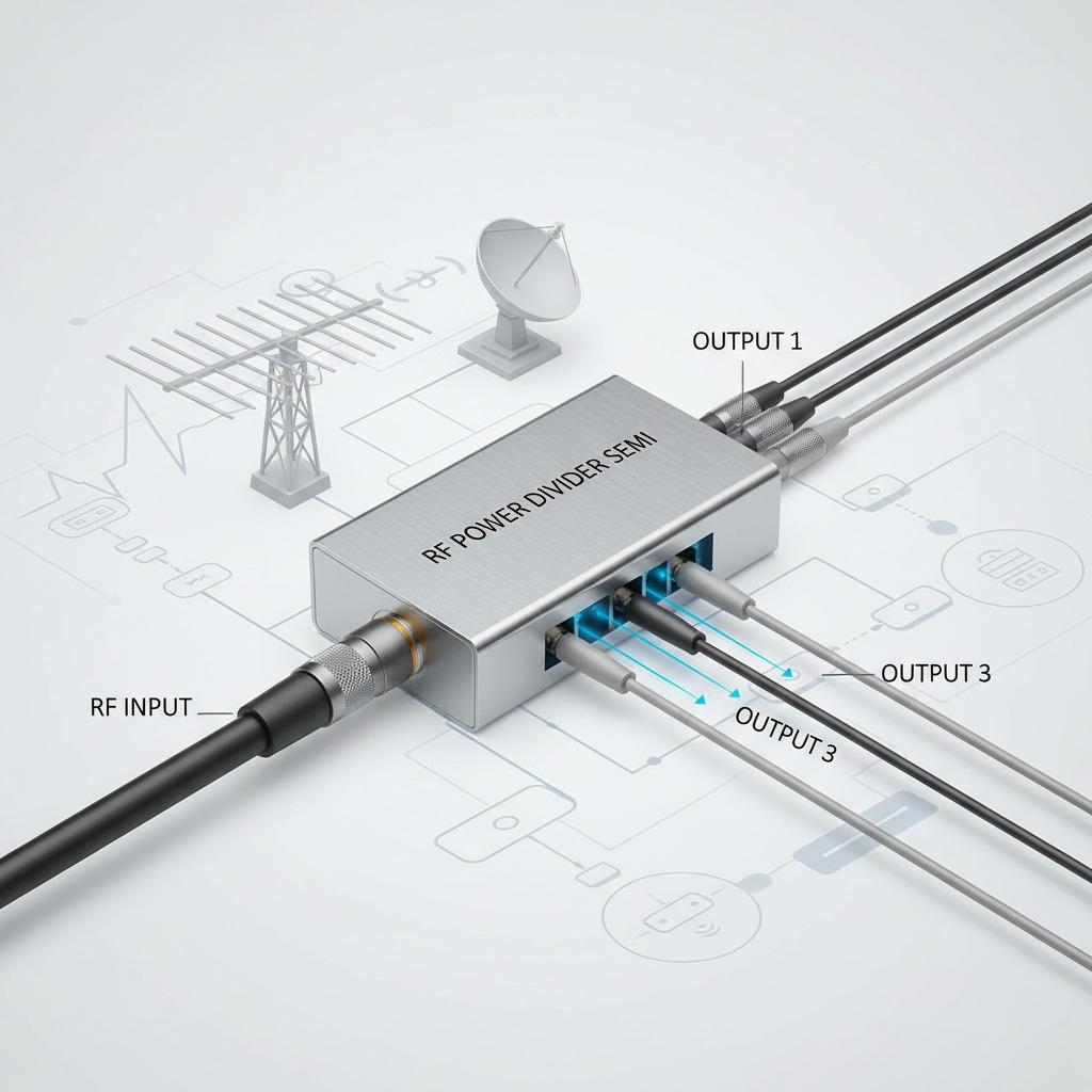
In the world of radio frequency (RF) engineering, the semi power divider stands out as a crucial device for managing signal distribution efficiently. This component ensures that power from a single source is divided into multiple paths without significant loss, making it indispensable in telecommunications and broadcasting setups. As we delve into the intricacies of the semi power divider, we'll explore its design principles, applications, and how it integrates with related technologies like power divider circuits and RF power divider systems.
The Fundamentals of Semi Power Dividers
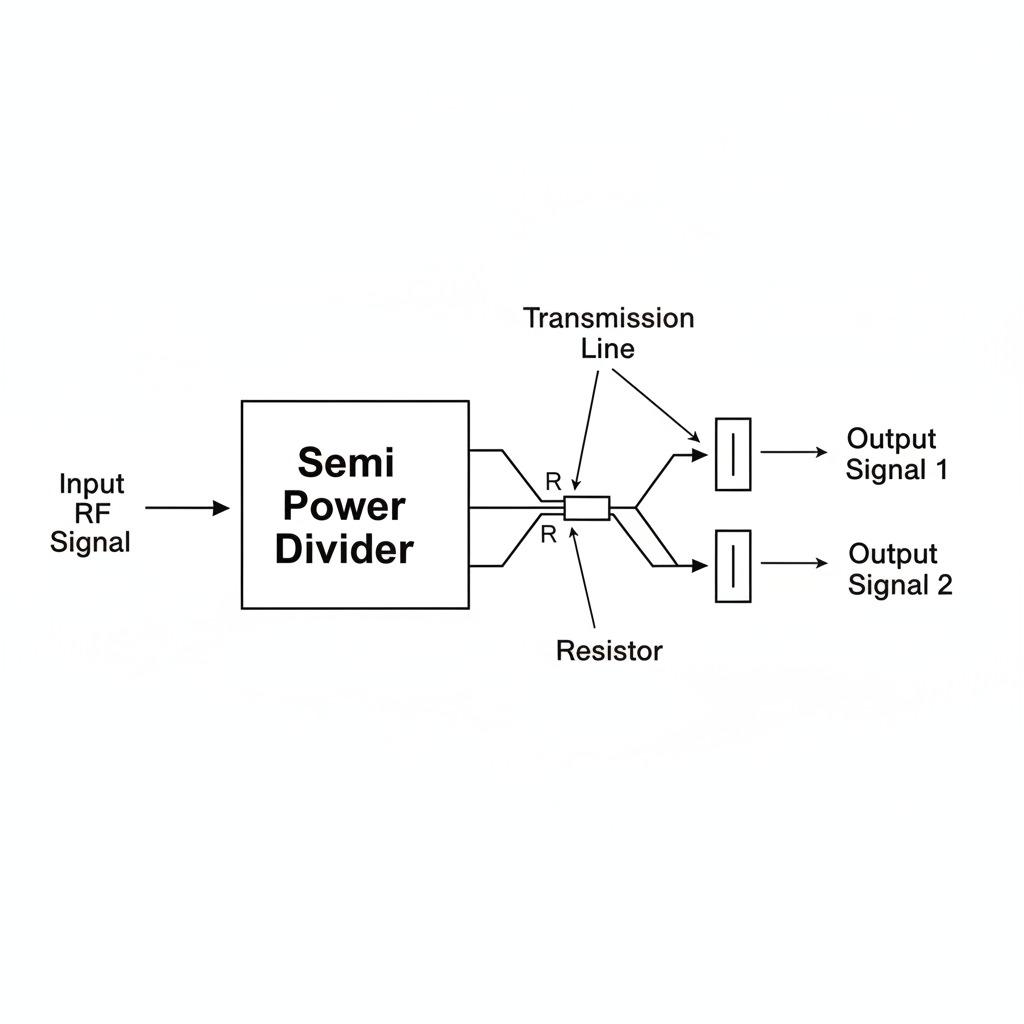
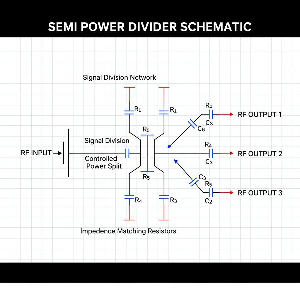
A semi power divider operates by splitting an input signal into two or more output signals with equal or specified power levels. Unlike full power dividers that aim for perfect isolation, the semi power divider offers a more practical approach, balancing performance and cost. This makes it ideal for applications where absolute isolation isn't critical, such as in amateur radio setups or basic RF testing environments. The design typically involves transmission lines or lumped elements configured to achieve the desired division ratio, often 2-way or 4-way splits.
Power divider circuits form the backbone of these devices. These circuits can be passive or active, with passive versions like the semi power divider relying on resistors, capacitors, and inductors to manage impedance matching. Impedance matching is key here; without it, reflections can degrade signal quality. For instance, a well-designed semi power divider maintains a 50-ohm impedance across ports, ensuring minimal voltage standing wave ratio (VSWR) for clean signal propagation.
In practice, engineers select semi power dividers based on frequency range, typically from HF to microwave bands. Their semi-rigid construction—hence the name—allows flexibility in coaxial cable implementations, making them adaptable to various mounting configurations. This versatility is why they're favored in prototype development, where quick adjustments are necessary.
Exploring RF Power Dividers in Modern Applications
The RF power divider is an evolution of basic splitting technology, optimized for high-frequency operations in wireless communication systems. These dividers are essential in antenna arrays, where multiple elements need synchronized signals to form directional beams. A semi power divider can serve as a cost-effective alternative in less demanding RF setups, such as satellite downlinks or radar subsystems.
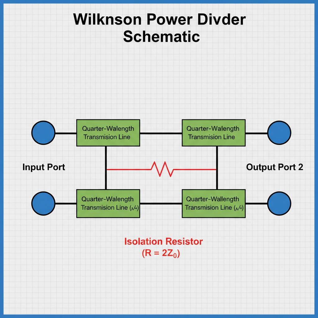
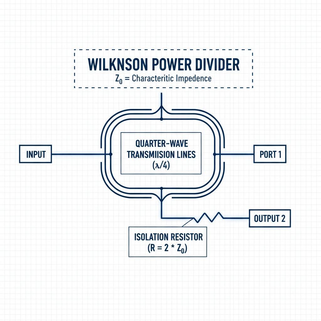
One of the primary advantages of integrating a semi power divider into RF power divider networks is the reduction in signal attenuation. Traditional Wilkinson dividers, for example, provide excellent isolation but at the expense of bandwidth. In contrast, semi power dividers offer broader bandwidths, often up to several gigahertz, making them suitable for 5G infrastructure or IoT devices. Power divider circuits within these systems must handle power levels from milliwatts to kilowatts, depending on the application.
Consider a scenario in mobile base stations: an RF power divider splits the transmitter's output to feed multiple antennas, enhancing coverage. Here, a semi power divider ensures even distribution, preventing hotspots that could lead to interference. Maintenance is straightforward, with modular designs allowing easy replacement without disrupting the entire network.
Moreover, advancements in materials like low-loss dielectrics have improved the efficiency of semi power dividers. They now support higher power handling, up to 100W or more, without overheating. This reliability is critical in aerospace applications, where failure isn't an option.
Design Considerations and Integration Challenges
When designing systems around a semi power divider, several factors come into play. Phase balance is paramount; outputs should maintain consistent phase shifts to avoid destructive interference. Power divider circuits achieve this through symmetrical layouts, ensuring each path experiences identical electrical lengths.
Challenges arise in miniaturization for compact devices. RF power dividers in smartphones or wearables demand small footprints, pushing engineers toward microstrip or stripline implementations of semi power dividers. These configurations reduce size while preserving performance, though they require precise fabrication to avoid parasitics.
Testing a semi power divider involves vector network analyzers to measure insertion loss, return loss, and isolation. Ideal specs include less than 0.5 dB insertion loss and over 20 dB isolation between ports. In power divider circuits, cascading multiple semi power dividers can create complex networks, like Butler matrices for beamforming, but this amplifies losses if not carefully managed.
Environmental factors also influence selection. For outdoor RF installations, semi power dividers with rugged enclosures protect against weather, ensuring longevity in harsh conditions.
Advanced Uses and Future Trends in Power Division
Beyond basics, semi power dividers find roles in combiner applications, where signals from multiple sources merge into one. This duality—dividing and combining—makes them versatile in amplifiers and mixers. In power divider circuits for phased array radars, they enable electronic scanning, a technology pivotal to modern defense systems.
Looking ahead, the integration of semi power dividers with software-defined radios (SDRs) promises dynamic reconfiguration. Imagine an RF power divider that adjusts split ratios on-the-fly via digital controls, optimizing for varying signal conditions. This could revolutionize adaptive communication networks.
Emerging materials like metamaterials may further enhance semi power dividers, offering negative refractive indices for unprecedented bandwidths. As 6G research accelerates, these innovations will be key to handling terahertz frequencies.
In educational settings, understanding power divider circuits through hands-on projects with semi power dividers fosters innovation among students. Kits with adjustable components allow experimentation, bridging theory and practice.
Practical Tips for Implementing Semi Power Dividers
For hobbyists or professionals, start with simulation tools like Keysight ADS or Ansys HFSS to model your semi power divider before building. This virtual prototyping catches design flaws early. When sourcing components, prioritize those with specified frequency responses to match your RF power divider needs.
Assembly requires attention to soldering techniques, especially for high-frequency power divider circuits, to prevent micro-cracks that cause intermittent failures. Calibration post-assembly ensures optimal performance.
In summary, the semi power divider remains a cornerstone of RF engineering, offering reliable signal management through efficient power divider circuits. Whether in commercial RF power divider systems or custom designs, its role in enabling seamless connectivity cannot be overstated. As technology evolves, so too will the capabilities of these essential devices, paving the way for more advanced wireless ecosystems.
Frequently Asked Questions (FAQ)
1. What is the fundamental difference between a trench drain and a French drain?
A trench drain (channel drain) is a surface drainage system consisting of a prefabricated channel with a removable grate. It captures and conveys surface water runoff (rain, wash-down, melting snow) from paved areas like driveways, roads, and pool decks. Water enters through the grate and flows through the channel to an outlet.
A French drain is a subsurface drainage system consisting of a perforated pipe buried in a gravel-filled trench. It intercepts groundwater and seepage below the surface, lowering the water table to prevent soggy yards or basement flooding.
Key distinction: Use a trench drain for standing water on top of pavement; use a French drain for chronically wet soil or underground water intrusion.
2. How do I calculate the required size (width and depth) of a drain channel for my project?
Sizing a drain channel requires calculating the peak flow rate based on drainage area, rainfall intensity, and surface type. A simplified method:
-
Determine the drainage area (length × width of paved surface in square feet)
-
Use the rational formula: Q = C × I × A
-
Q = peak flow rate (cubic feet per second or liters per second)
-
C = runoff coefficient (0.9 for pavement, 0.3 for grass)
-
I = rainfall intensity (inches per hour – from local weather data)
-
A = drainage area (acres or square meters)
-
-
Select a channel with hydraulic capacity (published by manufacturer) that exceeds Q.
For residential driveways, a standard 4–6 inch wide channel with a 3–4 inch deep flow path is typically sufficient. For commercial or high-rainfall areas, wider (12+ inch) and deeper channels are required. Consult manufacturer sizing charts or a civil engineer for critical applications.
3. What is the difference between polymer concrete and fiberglass-reinforced plastic (FRP) drainage channels?
| Material | Composition | Strength | Weight | Chemical Resistance | Best For |
|---|---|---|---|---|---|
| Polymer concrete | Resin + aggregate (sand/gravel) | Very high | Heavy | Excellent | High-load areas, roadways, industrial yards |
| FRP (fiberglass) | Resin + glass fibers | High | Lightweight | Excellent (resists salts, acids, fuels) | Chemical plants, coastal areas, lightweight installation |
Polymer concrete is stronger under compression (ideal for vehicle loads). FRP is lighter and more flexible, making it easier to install but with lower point-load capacity. For residential driveways, polymer concrete is common; for corrosive environments (seawater, chemicals), FRP is preferred.
4. Can I drive a car or truck over a plastic drain channel grate?
It depends entirely on the load rating (Class A, B, C, etc.), not the material alone. Some heavy-duty plastic/polymer grates are rated for Class B (passenger cars) or even Class C (light trucks). However:
-
Standard residential plastic grates (Class A) – Pedestrian only; will crack under vehicle weight
-
Heavy-duty polymer concrete grates with Class B or C ratings – Safe for driveways
-
Cast iron or ductile iron grates – Required for Class D and above (roads, heavy commercial)
Rule: Always check the manufacturer's load rating label. Do not assume a plastic grate is vehicle-safe. For a standard home driveway, select a Class B or C rated grate regardless of material.
5. How do I prevent leaves, gravel, and sediment from clogging my underground drain pipe?
Install a sediment basket (debris trap or silt bucket) directly below the grate or at the channel outlet. These removable baskets capture:
-
Large debris – Leaves, twigs, mulch
-
Heavy sediment – Sand, grit, small gravel
-
Hair and soap scum (for indoor channels)
Maintenance: Lift the basket every 1–3 months (more frequently during autumn or after storms), empty contents into a trash bag, and reinsert. This simple device prevents 90% of underground clogs, eliminating the need for expensive pipe jetting or excavation.
For channels without integrated baskets, install an inline debris separator or a catch basin with a sump upstream of the pipe.
6. What slope do I need for a drain channel to function properly?
The minimum recommended slope for a drain channel to remain self-cleaning is 0.5% to 1% (1/16 to 1/8 inch per foot). However:
-
0.5% (1/16 inch per foot) – Minimum acceptable; water will flow but sediment may accumulate
-
1% (1/8 inch per foot) – Standard recommendation; provides positive flow and flushes fine solids
-
2% (1/4 inch per foot) – Ideal for channels with flat bottoms or low-flow conditions
How to verify slope: Use a string level or laser level stretched between the inlet and outlet points. Measure the drop. For a 20-foot channel at 1% slope, the outlet must be 2.4 inches lower than the inlet.
Critical note: A completely flat channel will not drain – it becomes a stagnant sediment trap. Always verify slope before backfilling and compacting around the channel. For retrofit projects with limited depth, use a low-profile channel designed for shallow slopes (some self-cleaning designs work at 0.3%).